星期五, 12月 21, 2018
發光樂高路克 與 美國太空筆
最近研究一個小東西,想把樂高的星際大戰路克光劍加上LED發光,這之前就完成了。
但是我想把路克搬到GOGORO 2上面去,之前剛好裝了樂高油缸蓋,帝國風暴兵已經佔領一陣子了,我希望路克上去平衡一下原力。
於是我就在想,這麼小的空間要供電,電池沒辦法太大,所以最好就是只有晚上且騎乘的時候發光就好(白天發光也看不到啊!)。因此我從555 Timer研究起,無奈覺得有點複雜,要達到我想要的功能可能要不止一顆555,還是回頭用我比較熟悉的Arduino吧。
這麼小的體積及簡單的功能用ATtiny13就可以了,用Uno當ISO燒錄器去燒錄ATtiny13也不是甚麼大問題。接著是加上震動偵測模組以及光敏電阻,就可以知道現在是否在騎乘、是否是晚上,用Pro mini加上一些範例,其實這些簡單功能幾十分鐘就完成,接下來就是把程式碼加上Power Saving功能並且轉移到ATtiny13就好了!
但是我突然覺得,挖勒...為了讓路克光劍發光,搞得這麼複雜幹嘛......
做個開關, 晚上騎車前按一下,下車再按一下,不就好了...............................
如此就只需要一個鋰電池、一個開關、一個限流電阻和拿著光劍的路克,完工!
為了避免額外的耗電,最後我把限流電阻改成CRD限流二極體。
最多再加一個USB鋰電池充電模組就好了。
這讓我想到一個故事,太空筆的故事。
傳說中美國太空總署花了好多錢做了一隻太空筆,為的就是可以在太空失重環境下書寫;而蘇聯用一支鉛筆就解決這個問題。這是個震撼人心的故事。
結果事實不是這麼一回事,有興趣的人請自己打開下面連結:
下面連結
總之,我想說的只有一句話:莫忘初衷
星期三, 8月 02, 2017
BLE Lego Train
I've been busy with BLE Lego Train recently.
Traditionally, we use 8879 Remote control IR Speed Remote Control to control most 4 trains.
But I also want to control auto switch tracks with motor , it's need more and more 8884 REMOTE CONTROL IR RECEIVER.
If I want control 4 train and 4 switch, I need 2 x Remote Control, 8 x IR Receiver, 4 x 88002 Train Motor, 4 x 8883 Medium Motor, 8 x Battery Box, cost $$$$$$$$$$....
The expenditure of motor is unavoid, but I want build more intelligent railway system, a IoT based system, IR is not a good choice.
A BLE based Remote Control is better.
At beginning, I use RFDuino, a Arduino ecology mcu with NRF51822, including Nordic privated Gazell Link Layer protocol(GZll), very easy to exchange data between BLE devices by GZll.
This my first prototype:
RFDuino with GZll is good, but only support 8 devices (with host, totally 9 devices), there is not enough expansion capability for me. So I begin to study next prototype.
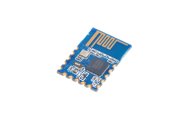
I found RedBear BLE Nano is a good candidate, acceptable price, and a most important: open source!
Open source that mean I can duplicate many BLE Nano compatible device with cheap NRF51822 board.
First I buy a set of RedBear BLE Nano for my 2nd prototype, I use RFDuino as RC host, to treat as a Beacon/Broadcaster. BLE Nano as RC device, to treat as a observer.
BLE Nano can receive advertisement data from Beacon, parse the data and interpreter command to control motor.
Now the path between RFduino and BLE Nano is linked, next step is controlling train motor directly!
![]() |
| 8879 Remote control IR Speed Remote Control |
Traditionally, we use 8879 Remote control IR Speed Remote Control to control most 4 trains.
But I also want to control auto switch tracks with motor , it's need more and more 8884 REMOTE CONTROL IR RECEIVER.
If I want control 4 train and 4 switch, I need 2 x Remote Control, 8 x IR Receiver, 4 x 88002 Train Motor, 4 x 8883 Medium Motor, 8 x Battery Box, cost $$$$$$$$$$....
The expenditure of motor is unavoid, but I want build more intelligent railway system, a IoT based system, IR is not a good choice.
A BLE based Remote Control is better.
At beginning, I use RFDuino, a Arduino ecology mcu with NRF51822, including Nordic privated Gazell Link Layer protocol(GZll), very easy to exchange data between BLE devices by GZll.
![]() |
| GZLL Star Network |
This my first prototype:
RFDuino with GZll is good, but only support 8 devices (with host, totally 9 devices), there is not enough expansion capability for me. So I begin to study next prototype.
I found RedBear BLE Nano is a good candidate, acceptable price, and a most important: open source!
| RedBear BLE Nano |
Open source that mean I can duplicate many BLE Nano compatible device with cheap NRF51822 board.
![]() |
| NRF51822 BLE GT82C01 |
First I buy a set of RedBear BLE Nano for my 2nd prototype, I use RFDuino as RC host, to treat as a Beacon/Broadcaster. BLE Nano as RC device, to treat as a observer.
BLE Nano can receive advertisement data from Beacon, parse the data and interpreter command to control motor.
Now the path between RFduino and BLE Nano is linked, next step is controlling train motor directly!
星期一, 6月 05, 2017
3.3v / 5v CanBus and TI HVD256
近來我的CanBus Project從Arduino ProMini平台轉移到Teensy 3.2平台, 因為Teensy3.2內建了CanBus Controller, 所以只要再外加一顆CanBus Transceiver( SN65HVD232 )就可以對CanBus做溝通. 且整體CanBus-ready的平台可以做得更小, 節省體積. 沒想到...這才是惡夢的開始...
我有兩套驗證CanBus用的Microchip MCP2551+2515, 接在一起:
Arduino-MCP2515-MCP2551 <---> CanBus <---> MCP2551-MCP2515-Arduino
用Teensy替代掉其中一套, 也就是變成這樣的架構:
Arduino-MCP2515-MCP2551 <---> CanBus <---> SN65HVD232-Teensy3.2
用來測試CanBus的正確性, 沒想到怎麼搞兩邊就是無法溝通. 讓我極度懷疑CanBus一邊3.3v一邊5v是不可行的, 但後來爬到這文章:
http://www.ti.com/lit/an/slla337/slla337.pdf
TI指出3.3v與5v CanBus是可以共存的, 卻讓我陷入了死胡同...
當然,最常遇到的終端電阻問題, 經過測試也排除掉了.
後來換把MCP2551替換成SN65HVD232, 讓CanBus直接走3.3V:
http://www.ti.com/lit/an/slla337/slla337.pdf
TI指出3.3v與5v CanBus是可以共存的, 卻讓我陷入了死胡同...
當然,最常遇到的終端電阻問題, 經過測試也排除掉了.
後來換把MCP2551替換成SN65HVD232, 讓CanBus直接走3.3V:
Arduino-MCP2515-SN65HVD232 <---> CanBus <---> SN65HVD232-Teensy3.2
還是失敗, MCP2515跟SN65HVD232間因為電壓不同, 似乎溝通上也有問題(個人推論, 並未驗證).
網路上爬文, 似乎也有不少人遇到跟我相同的問題:
https://e2e.ti.com/support/interface/industrial_interface/f/142/t/170788
https://www.amobbs.com/thread-3448321-1-1.html
http://www.microchip.com/forums/m851300.aspx
http://forum.arduino.cc/index.php?topic=173216.0
網路上爬文, 似乎也有不少人遇到跟我相同的問題:
https://e2e.ti.com/support/interface/industrial_interface/f/142/t/170788
https://www.amobbs.com/thread-3448321-1-1.html
http://www.microchip.com/forums/m851300.aspx
http://forum.arduino.cc/index.php?topic=173216.0
有人說是供電問題, 有人說是軟體問題, 但Teensy最終是要接車上的CanBus, 而非MCP2515/2551, 所以我也不想去處理MCP2515跟SN65HVD232間的問題.
不過就算把Teensy + SN65HVD232 接到車上CanBus也是無法溝通, 車上CanBus應該是走5V, 或許依舊是電壓造成的問題. 有一段時間就擱置下Teensy這個平台的使用計畫...
擱置將近一年後, 我臨時興起做了個實驗, 在底下的這架構, 把CanBus BitRate從500K降到20K, 居然通了!!
Arduino-MCP2515-MCP2551 <---> CanBus <---> SN65HVD232-Teensy3.2
但是再高一點就會一直傳錯, 開始懷疑是線材的問題(我是隨便拿兩條杜邦線來當CanBus High/Low). 但我不想處理線材問題, 會牽扯到我不太熟悉的類比領域, 有點超出side project的意義了. 所以我試著去找有沒有3.3v MCU(Teensy 3.2)可以用的5V CanBus Tranceiver??
很幸運的TI的CAN Reference Guide讓我找到一個方向:
HVD256正是我想要的解答, 它基本上是以5V運作(所以CanBus也是走5V), 但RX的部分可以相容3.3V的MCU(內建Level shifter), 所以接上3.3V Teensy是沒問題的. 這是一顆比較新的IC, 國內露天基本上是找不到現貨, 看來只能淘寶了... 但很幸運的是, TI非常佛心可以提供少量Sample, 而且還是Fedex寄出, 拿到這顆HVD256後替換HVD232, 居然通了!!!
http://www.ti.com/product/SN65HVD256/samplebuy
只是我在想, TI這顆HVD256不就直接打臉自己? 3.3V跟5V CanBus在某些條件下是無法相容??? 這個疑惑就留給有心人來解析了.... 臣,告退......
拉哩拉雜打了這麼多, 其實只有一個重點:
若你遇到3.3V跟5V CanBus無法溝通的問題, 試試看先讓它們電壓一樣吧!
星期四, 2月 25, 2016
LED名片拆解
最近買了一個LED名片, 想了解一下他的驅動方式, 買回來第一天就被我分屍了, 分屍前的照片還來不及拍... 只剩下這張屍塊組合照...
這咚咚是超音波熔接的, 非常難拆, 只能慢慢用筆刀劃開, 再用一字起子撬開.....
前方搭載了紅色濾光片, 對於判讀起了非常大的幫助, 若沒有濾光片, 光是LED本身的反光就夠亮的了.
濾光片完全拆除, 字幾乎看不清楚...
再來是最重要的背部, 很可惜不是採用ATMEL的solution. 採用的是GD32F150/C8T6的ARM mcu: http://www.gsense.com.cn/pro_detail.asp?id=139
LQFP封裝, 48pin, 支援高達39個GPIO.
本來以為買來會是採用ATMEL的solution, 這樣就可以把ATMEGA mcu刷成Arduino來玩玩了. 但是ATMEGA就沒那麼多IO可用, 所以要配置可觀的74HC595(就圖上應該有6顆), 如此cost也就低不下來.
以這個LED名片來看, 是四字的配置, 高度為11點, 因此總共有11x11x4 = 484點.
以傳統的掃描驅動方式需要44個IO(22x22 = 484).
ATMEL搭配6顆74HC595的, 每顆74HC595可以將3個IO擴充成8個IO, 因此18個IO可以擴充成48個IO, 可以驅動多達 24*24 = 576顆LED. 因此應付這個LED名片的484點是足夠的.
反觀GD32F150也無法驅動這麼多LED, 但也沒看到其他IC, 因此可能採用的就是Charlieplexing的驅動方式. 應用Charlieplexing只需要23pin就可以驅動507顆LED(23*23-23 = 506), 對GD32F150來說提供23個IO綽綽有餘.
雖然GD32F150 cost低, 但是採用的Charlieplexing本身掃描頻率比Multiplexing高很多, 但也因此單位時間內的LED發光次數會降低, 也就是LED亮度會比較低.
有機會再找找ATMEL solution的LED名片來分屍!
星期日, 1月 10, 2016
Use Arduino STM32 with Maple mini
Maple Mini
Maple mini is a phased out product, a STM32 based product with cheap price(about 5USD or 150NTD).
Official Maple IDE is not bad, but no longer support to win7, and driver with IDE is not signed, win7 deny install the driver without signed. It make Maple mini be a junk after win xp os.
Arduino STM32
There are some replacement package can let maple mini alive with win7 os:- Arduino Support Package For Maple
- STM32F103 and Maple / Maple Mini with Arduino 1.5.x IDE
- Arduino STM32
The best choice is method 3: "Arduino STM32", because it's based on method 1&2, and still active project.
It's a package to run with Official Arduino IDE, so you need to download the Arduino IDE and install. The newest version 1.6.7 maybe is not a good choice, because I had some problem when compiling sketch. Version 1.6.5 is ok and Arduino STM32 official site say support it.
Install Arduino STM32
Download Arduino STM32 and decompress, recommend to put whole directory to "~your sketch directory/hardware/" , named it to "Arduino_STM32" or whatever you like.
Install the driver first by "Arduino_STM32/drivers/win/install_drivers.bat".
Run Arduino IDE, now you can seed Maple Mini in Board:
Bootloader
If your Maple Mini is original, you should select Original Bootloader.
It's recommend to update to Bootload 2.0 (bootload with Arduino STM32).
You can update by a updating sketch from Arduino STM32's site. You can download it by this link. And Follow these step:
- Upload "updating sketch" by Arduino IDE with Original Bootloader version.
- Open Serial Monitor, you can see some warning message, press Y and send it.
- Wait some updating message, reset it,
Happy Arduinoing with Maple Mini !!!!
星期五, 11月 20, 2015
UART over Wifi by NodeMCU (Programming NavSpark via ESP8266)
動機
NavSpark是個包含GPS功能的Arduino相容版, 詳情請看我之前的網誌: NavSpark Mini初體驗 .會選用這片做為Arduino, 想必會用到上面的GPS功能, 但麻煩的是, 每次coding燒錄完之後, 若要確定程式正確, 勢必得挑一個可以收到GPS訊號的地方. 我當然大可以帶著筆電和NavSpark去外面coding, 但在寒冷的晚上又要餵蚊子, 不是個很好的coding環境.
又或者我可以拉一個GPS天線到室內, 然後接上NavSpark的IPX接頭.
串列埠轉WIFI模組 UART to WiFi EM-380C(BB-MAXCHIP) NT$3,300
A06-0029 UART轉WIFI模組 NT$1890
以上兩個方法似乎都不是很好的方式, 後來我想到UART X Wifi的方式, 這當然不是甚麼先進的想法, 一些天文觀測的同好早就用這樣的方式, 在室內/帳棚內輕鬆遙控寒冷星空下的望遠鏡.
但是這類的周邊通常都不太便宜(當然淘寶找可以便宜很多....), 若只是為了開發驗證用, 這樣的開銷划不來.
A06-0029 UART轉WIFI模組 NT$1890
剛好我手邊有片ESP8266 Wifi模組, 又具備UART的功能, 看來只要適當的設定就可以達到UARTx Wifi ! 而且這片ESP8266只花費百圓餘而已!
[2]Com0Com v3.0.0.0 utility for W7 x86 (32bit) platform, signed driver.
com0com/com2tcp
透過com0com/com2tcp的方式, 可以省略掉USB-Serial, 但是需要多一個WIFI Adapter, 不過若是用NB, 應該不會缺乏WIFI Adapter.
本文是朝向使用com0com/com2tcp的方向規劃.
另外, com0com官網上的安裝檔附的驅動不含簽名, 在win7下是無法使用的, 建議可以改下載[1]或[2]的com0com安裝檔進行安裝.
NodeMCU
根據[3], ESP8266可以用AT Command/NodeMCU/原生SDK/Arduino等方法開發(WebSDK就不適用於這裡的用途了, IoT比較適合).
看來比較適合且不用花太多時間的就屬NodeMCU和Arduino, 其中NodeMCU是以script方式執行, 可以略過編譯及燒錄的冗長時間, 最後NodeMCU出線.
為了用上NodeMCU, 需要先將Node MCU Firmware燒錄到ESP8266, 可以參考[3]的說明操作.
Telnet Server
由於com2tcp支援telnet協定, 因此ESP8266端運行一個telnet server, 將接收到的訊息傳送到UART, 再將UART發出的訊息回送到telnet client, 如此就可以做到雙向溝通.
運行在NodeMCU上的telnet我是以[4]為基礎下去修改. 結果下面會提到.
首先NodeMCU將init.lua及wifi.lua設定為以下內容:
--init.lua
dofile("wifi.lua")
--wifi.lua
print("set up wifi mode")
wifi.setmode(wifi.STATION)
wifi.sta.config("skyforce","0913679376")
--here SSID and PassWord should be modified according your wireless router
wifi.sta.connect()
tmr.alarm(1, 1000, 1, function()
if wifi.sta.getip()== nil then
print("IP unavaiable, Waiting...")
else
tmr.stop(1)
print("Config done, IP is "..wifi.sta.getip())
--dofile("yourfile.lua")
end
end)
telnet server的script如下, 但不建議一開始就放在init.lua直接執行, 因為執行script後, UART會直接轉向telnet, 因此NodeMCU無法再透過UART被操作, 等於NodeMCU會變成磚(只剩下UART轉Wifi的功能), 除非重燒韌體.
所以請先用手動執行的方式, 確認整個環節都打通了, 再把telnet server script放到init.lua讓他開機自動執行.
telnet.lua[4]:
--simple_telnet.lua
baudrate = 115200
telnet_port = 23
uart.setup( 0, baudrate, 8, 0, 1, 0 )
s=net.createServer(net.TCP,60)
s:listen(telnet_port ,function(c) --c : net.socket module
--send
function s_output(str)
if(c~=nil)
then c:send(str)
end
end
--node.output(s_output, 0) -- re-direct output to function s_ouput.
uart.on("data", 0, s_output, 0)
--receive
c:on("receive",function(c,l)
--node.input(l) -- works like pcall(loadstring(l)) but support multiple separate line
uart.write(0,l)
end)
-- disconnect
c:on("disconnection",function(c)
node.output(nil) -- un-regist the redirect output function, output goes to serial
end)
end)
若要NodeMCU開機時就啟動telnet server, 將init.lua改為:
--init.lua
dofile("wifi.lua")
dofile("telnet.lua")
com0com/com2tcp的設定
com2tcp則按照下面的參數執行
com2tcp --baud baudrate \\.\com## ip port
baudrate的部分照NavSpark UART的baudrate去設定即可, NavSpark mini的UART預設為115200, 因此我也設定在115200, 但115200用來燒錄其實很慢.
com##則要看com0com安裝時配給的com來決定, 依照我的環境設定COM16, 而COM15提供給Arduino或GNSS Viewer燒錄用.
ip則填入NodeMCU跟ap所取得的ip.
port則按照telnet標準port為23.
GNSS Viewer燒錄時可以改變原本的baudrate, 縮短燒錄時間, 但這一招用在UART x Wifi似乎行不通, 比較可能的解釋是這樣的:
在原本的架構下, GNSS Viewer通知NavSpark改變baud rate, 然後comA接著更改到相同的baud rate, 兩邊就可以用新的baud rate繼續溝通
但是當我們採用Wifi的方式燒錄, 架構中共有三個UART設定, GNSS Viewer可以改變UART1, NavSpark也改變了對應的baud rate, 但是com2tcp對應的UART2及ESP8266對應的UART3卻沒有跟著改變, 因此整個UART並沒有用相同的baud rate去運行, 因此整個baud rate改變的機制無法正常運作.

暫時想不到解決方法, ESP8266或許可以攔截UART訊號去改變baud rate,但是com2tcp該怎麼作到動態改變baud rate我就不知道了. 目前最快的方式, 可能是直接將UART1/2/3的baud rate設高一點縮短燒錄時間.
com2tcp若不開啟 baud rate emulation, 是可以不用care baud rate設定, 參考自這裡. 因此UART2的設定可以don't care.
com##則要看com0com安裝時配給的com來決定, 依照我的環境設定COM16, 而COM15提供給Arduino或GNSS Viewer燒錄用.
ip則填入NodeMCU跟ap所取得的ip.
port則按照telnet標準port為23.
GNSS Viewer燒錄問題
在原本的架構下, GNSS Viewer通知NavSpark改變baud rate, 然後comA接著更改到相同的baud rate, 兩邊就可以用新的baud rate繼續溝通
但是當我們採用Wifi的方式燒錄, 架構中共有三個UART設定, GNSS Viewer可以改變UART1, NavSpark也改變了對應的baud rate, 但是com2tcp對應的UART2及ESP8266對應的UART3卻沒有跟著改變, 因此整個UART並沒有用相同的baud rate去運行, 因此整個baud rate改變的機制無法正常運作.

暫時想不到解決方法, ESP8266或許可以攔截UART訊號去改變baud rate,
com2tcp若不開啟 baud rate emulation, 是可以不用care baud rate設定, 參考自這裡. 因此UART2的設定可以don't care.
[參考]
[1]Com0Com v3.0.0.0 utility for W7 x64 platform, signed driver.[2]Com0Com v3.0.0.0 utility for W7 x86 (32bit) platform, signed driver.
[3]ESP8266 韌體概述
星期三, 11月 04, 2015
ESP8266 ESP-201 X Arduino
網路上較少ESP-201當Arduino的中文文章, 所以每次要接線都要翻閱資料許久. 英文資源雖不少, 但每次重看都需要稍微消化一下才懂.
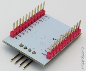
這張全pin引出, 且可安裝在麵包版的ESP-201(雖然需要小小改造一下), 是很適合拿來開發的板子. 我把開發ESP-201的基本設置筆記如下, 方便記性不太好的我可以翻閱.
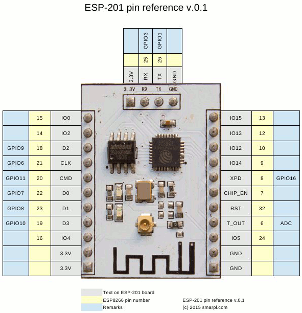
另外ESP-201上面標示的pin-out也跟一般ESP8266不一樣, 必須了解一下對應關係....
幸好已經有心人整理出下面這些圖[1]:
註: 後來發現node.info()讀出來的值, 跟當初燒錄韌體時的設定是連動的, 也就是說這裡的值是設定好的, 未必直接關連到板子上的flash.
若你是用NodeMCU的燒錄工具, node.info()的值則直接關連到下圖的設定值:
[參考]
http://www.areresearch.net/2015/05/flashing-running-esp-201-module.html
ESP8266 ESP-201 module - antenna troubleshooting
這張全pin引出, 且可安裝在麵包版的ESP-201(雖然需要小小改造一下), 是很適合拿來開發的板子. 我把開發ESP-201的基本設置筆記如下, 方便記性不太好的我可以翻閱.
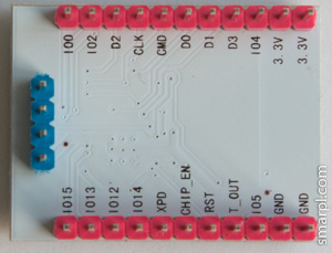
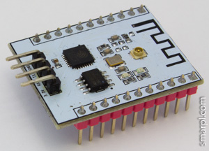
ESP-201 header改造
ESP-201這張模組雖然拉出所有pin-out很方便, 但犯傻做錯了兩件事情:
- RX/TX的header方向讓ESP-201無法安裝在麵包板上
- 把pin的名字印在電路板的背面, 這樣裝上麵包板誰看的到
或許一開始設計就不打算讓大家裝在麵包板上.......
首先要解決第一個問題, 根據[2], 把RX/TX的header焊到另外一端即可, 或者你要更搞剛把兩個11-pin header焊到另外一邊, 這樣上述兩個問題就一次解決.......否則就照下圖的方式修改[2]:
before
after
ESP-201接線
但是ESP8266 Arduino官網卻沒提到如何燒錄/連結ESP-201的資訊, 這讓我有點頭痛.另外ESP-201上面標示的pin-out也跟一般ESP8266不一樣, 必須了解一下對應關係....
幸好已經有心人整理出下面這些圖[1]:
ESP8266 Arduino官網提到Generic ESP8266的連接方法[3]:
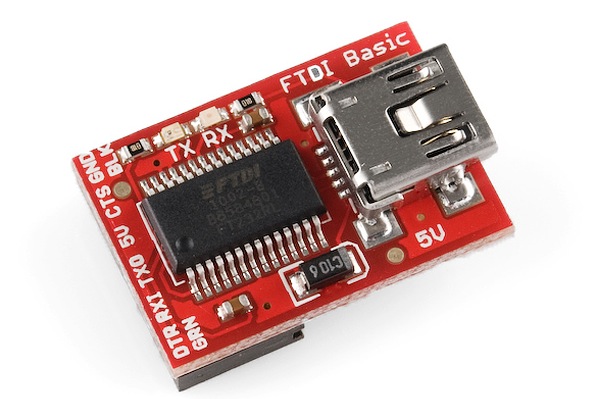
但是這個方法需要USB-Serial可以拉出RTS, 以便控制ESP8266 Reset. 我手邊的USB-Serial都沒有拉出RTS, 像這種:
全部pin-out都有拉出的模組是比較適合搭配ESP-201的:
若你的USB-Serial也沒有RTS, 可以手工焊上鍍銀線把RTS拉出來, 但是沒地方可固定感覺不是很穩固, 只好作罷. 後來找到這張表:
模式
| GPIO | ||||
| 15 | 2 | 0 | |||
| 1 | SDIO | 1 | x | x | 系統工作在 SDIO 模式, 可以用外部 MCU 驅動内部WIFI |
| 2 | 工作模式 | 0 | 1 | 1 | 系统從外部FLASH 啟動 |
| 3 | 燒錄模式 | 0 | 1 | 0 | 系统自動進入升級狀態,等待Serial-port下達命令 |
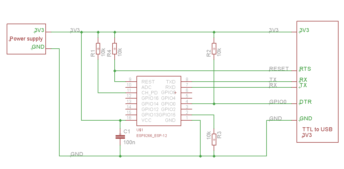
照表操課, 如果要燒錄的話, 要這樣接[2]:
GPIO0和GPIO15有接地即可燒錄. GPIO2可能內部有上拉電阻(?), 所以沒接也ok.
但每次上電後只能燒錄一次, 若要再燒錄必須斷電, 或者讓 RST接地讓ESP-201Reset.
我是直接拉出RST到微動開關,微動開關接地, 再加一個上拉電阻10k確保不會沒事Reset, 這樣每次要重新燒錄前, 按一下微動開關就好了.
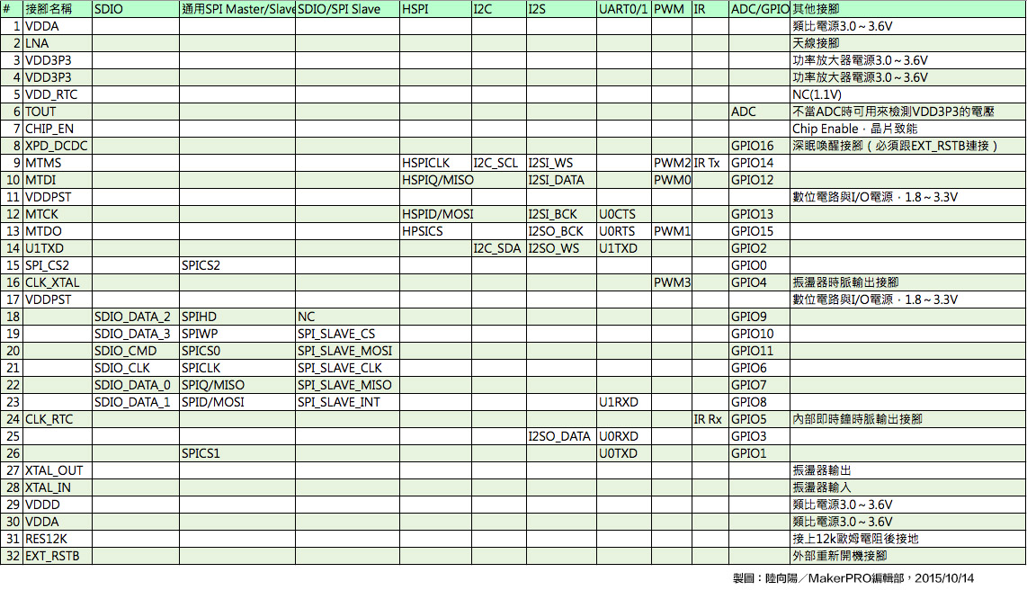
還有人將ESP8266所有pin-out整理成一張非常棒的表[4], 開發時接線很方便:
我試著將上述幾張表整合成一張, 方便查詢:
Arduino IDE環境設置
接好線後, 設置ArduinoIDE環境, 我是使用 Arduino core for ESP8266 WiFi chip 提供的core, Board Manager URLs 為:
http://arduino.esp8266.com/stable/package_esp8266com_index.json
安裝好官方Arduino IDE後, 再設定Boards Manage即可使用. 細節請直接見 Arduino core for ESP8266 WiFi chip官網.
http://arduino.esp8266.com/stable/package_esp8266com_index.json
安裝好官方Arduino IDE後, 再設定Boards Manage即可使用. 細節請直接見 Arduino core for ESP8266 WiFi chip官網.
ESP-201燒錄
從node.info()讀出來的訊息[2]:
| flash size(byte) | flash mode (SPI mode) | flash speed(Hz) |
| 512 | 0 | 40000000 |
但我後來發現, 每一片ESP-201的flash不一定一樣, 同樣從node.info()讀出來, 我手上的ESP-201 flash參數如下:
| flash size(byte) | flash mode (SPI mode) | flash speed(Hz) |
| 512 | 2 | 20000000 |
其中flash mode的部分不太確定數字對應的意義, 若參照[5]的說明:spi mode(0=QIO, 1=QOUT, 2=DIO, 3=DOUT)
若你是用NodeMCU的燒錄工具, node.info()的值則直接關連到下圖的設定值:
Arduino IDE燒錄時的設定應該如下:
Flash Frequency的地方, 預設只有40和80MHz, 額外的頻率需要自行設定, 在 AppData\Roaming\Arduino15\packages\esp8266\hardware\esp8266\1.6.5-947-g39819f0 的目錄下(可能因為esp8266-arduino版本不同而目錄名稱略有不同), 編輯 boards.txt:
找到FlashFreq的欄位, 新增20/26.7兩種頻率即可.
- ESP8266 ESP-201 module - first impressions
- ESP8266: ESP-201 breakout board review
- Generic ESP8266 modules
- ESP8266之GPIO功能、資源探索
- MOD-WIFI-ESP8266 Reflashing question
http://www.barissanli.com/electronics/nodemcu.php
ESP8266 ESP-201 module - antenna troubleshooting
星期三, 8月 26, 2015
NavSpark Mini初體驗
NavSpark是之前在indiegogo上集資成功的專案, 成品是Arduino+GPS, 32bit mcu, 並且體積相當小(大概就Arduino Nano的大小)
之後出了一片NavSpark mini, 是NavSpark的相容版, 硬體規格一樣, PCB更小, 當然pin out也比較少, 但是一些小專案應該夠用了, 而且還是內建GPS receiver (但是天線要外接)
現在原廠在推廣NavSpark mini, 索取一片只需要運費9usd, 非常划算.
我週五下單, 隔周三就到貨, 收的是國際運費, 但是用的是本地快遞(新竹寄到新竹), 就當作用運費贊助這間公司了(有附發票XD).
收到貨後有兩片PCB, 分別是NavSpark mini主板以及USB-UART轉板, 這片轉板是走Android手機常用的micro USB而非mini USB, 電平3.3V, 接上吃3.3V的NavSpark mini的剛剛好.
若是用自己的USB-UART轉板, 就要特別注意電壓的部分, 免得把NavSpark mini燒了
接著就是準備開發環境, 首選當然是Arduino IDE, 但是Arduino IDE原生是不支援NavSpark mini的, 你有兩種選擇:
- 從NavSpark官網下載支援的Arduino IDE 1.5.6 載點
- 從Boards Manager下載NavSpark的支援 NavSpark原廠說明
按照原廠接線圖接好, 就可以用Arduino IDE燒錄了.
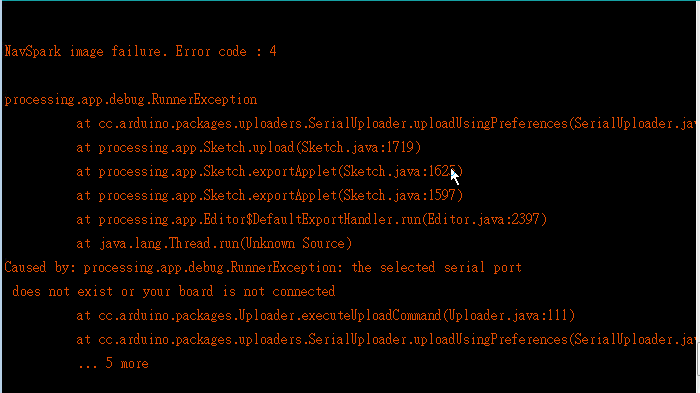
剛玩了一下就出問題, 怎麼樣都燒不進去
如果燒錄時選擇不要GNSS library, 就不會有boot-loader(所以boot-loader是放在GNSS library裡面的....), 那下一次就無法讓Arduino IDE直接透過USB做燒錄的動作.
(我不懂這樣的邏輯是甚麼, 誰說不要GNSS就用不到boot-loader? )
The Non-GNSS library does not have boot-loader code within, thus program compiled with Non-GNSS library needs to run from recovery ROM mode to load code
NavSpark的boot方式有ROM Mode以及Flash Mode, 對應mcu韌體的載入來源.
如果沒有燒boot-loader到Flash, 就只能改用ROM Mode還原boot-loader,
為了改用ROM Mode, NavSpark mini的BOOT_SEL就身負這樣的重責大任
如果沒有燒boot-loader到Flash, 就只能改用ROM Mode還原boot-loader,
為了改用ROM Mode, NavSpark mini的BOOT_SEL就身負這樣的重責大任
BOOT_SEL: Default unconnected, internally pulled-high, Venus822A runs program from internal Flash memory. Whenconnected to GND, Venus822A runs program from internal ROM memory. When improperly written user code hangsthe system, it would be necessary connect BOOT_SEL to GND and recover from ROM mode to load corrected code.
所以short BOOT_SEL到GND, 就可以讓NavSpark mini從ROM memory拉回原本預先燒好的code, 當然boot-loader也包含在內, 只要遵循以下的步驟:
1. Connect BOOT_SEL pin to GND to run program off internal ROM memory.
2. Check state of GPIO4 and GPIO5, these two pins determine baud rate used for UART1 (USB) communication when
booting from internal ROM memory. See next section on how to set command and code upload baud rate to use
for Arduino IDE in case GPIO[5:4] connected to differ from default 2’b11.
GPIO[5:4] = 2’b00 for 9600
GPIO[5:4] = 2’b01 for 4800
GPIO[5:4] = 2’b10 for 38400
GPIO[5:4] = 2’b11 for 115200 (default)
3. Press the reset button and release it to restart the LEON3 processor.
4. Use Arduino IDE to do the code upload procedure with the correct binary code.
5. Once code upload completes, disconnect BOOT_SEL from GND to run from Flash memory, press the reset button
and release it to restart.
到此應該可以正常燒錄了?!
其中標示紅色的第二步驟最為重要, 由於GPIO4/5決定ROM Mode的baud-rate, 在不設定的狀況是被認定為接地的, 所以預設的baud-rate會是9600, 用Arduino IDE因為baud-rate設定不同事無法燒錄的.
因此需要在未上電的狀況下, 將GIPO4/5接在3.3V再上電, 確保GPIO[5:4]是在高電位讓baud-rate設定在115200bps.
若已經上電再去接GPIO4/5後reset是沒有效果的.
如果用不到GNSS library, 這樣每次燒錄就是要不斷的short BOOT_SEL, reset... 燒錄....
如果不差GNSS library佔掉的記憶體的話, 我看燒錄還是直接放GNNS library進去吧...
[附註] NavSpark Error code對應的意義(參考這裡):
1 - Can't open firmware binary file.
2 - Parameter error, unsupported baud rate.
3 - Can't open COM port.
4 - Sent download command but receive no ACK response
6 - Loader program sent binary file size command but receive no ACK response
7 - Sent firmware in 8KByte block but receive no ACK response
8 - No END command received, denoting Flash checksum error
[資源]
訂閱:
文章 (Atom)
iPhone 14 Pro vs Olympus EM10 MkII 中篇
時間來到2022年, 我的S20+因為綠線事件, 立馬被我淘汰了, 同時我也正計畫購入Mini Countryman, 很殘念的是該車系統只支援CarPlay而不支援Android AUTO, 所以我也開始考慮要不要從Android換到Apple陣營. 好, 上面都是題外話, 反...
-
http://www.instructables.com/id/Uploading-sketch-to-Arduino-Pro-Mini-using-Arduino/ In above article we can use Uno to burn Pro Mini, but...
-
Android官方的IDE已經從Eclipse轉移到Android Studio了, OsmAnd官方建議的IDE還是在Eclipse , 看來要在 Android Studio下編譯OsmAnd要花點時間研究一下了, 況且官方文件非常缺乏=.= 經過我整理和簡化之後, 照以...
-
我總共擁有過兩台國際版的小米盒子, 一台是Mibox3(MDZ-16-AB), 另外一台是Mibox S(MDZ-22-AB). 其中我都是使用Kodi來做Lossless訊源的輸出(也稱為Pass-throught,也就是將Lossless音源不經解碼直接HDMI輸出). 一...